Engineering Software
Diesel Cycle Analysis
Diesel Cycle
Introduction
This section provides a Diesel Cycle analysis when the working fluid is air.
Analysis
In the presented Diesel Cycle analysis, only air is considered as the working fluid behaving as a perfect gas -- specific heat has a constant value. Ideal gas state equation is valid -- pv = RT.
Air enters a cylinder at point 1 when compression starts and it ends at point 2. Isentropic compression is considered with no entropy change. Heat addition starts at point 2 and it ends at point 3. At a constant pressure, air gets heated and the working fluid temperature raises. Expansion starts at point 3 and it ends at point 4. Isentropic expansion is considered with no entropy change. Air heat rejection starts at point 4 and it ends at point 1. At a constant volume, air gets cooled and the working fluid temperature decreases. It should be mentioned that air at point 1 enters the compression process again and the cycle is repeated.
Figure 1 contains a Diesel Cycle pressure vs volume diagram.
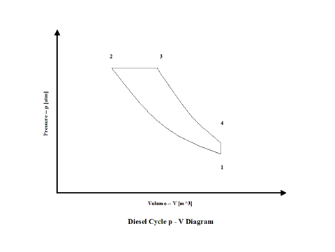
Figure 1 - Diesel Cycle Pressure vs Volume Diagram
Figure 2 presents a Diesel Cycle temperature vs entropy diagram.
Figure 2 - Diesel Cycle Temperature vs Entropy Diagram
Figure 3 presents the Diesel Cycle efficiency as a function of the compression ratio and a cut off ratio. It should be noted that the inlet conditions are standard ambient conditions: temperature of 298 [K] and absolute pressure of 1 [atm].
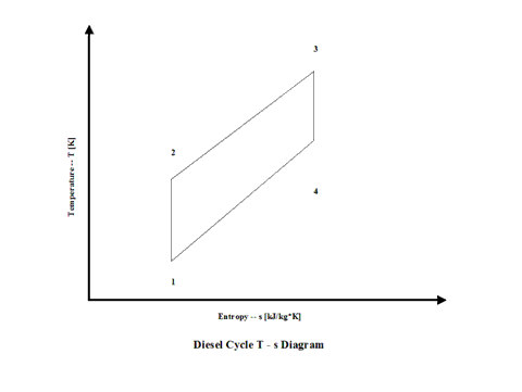
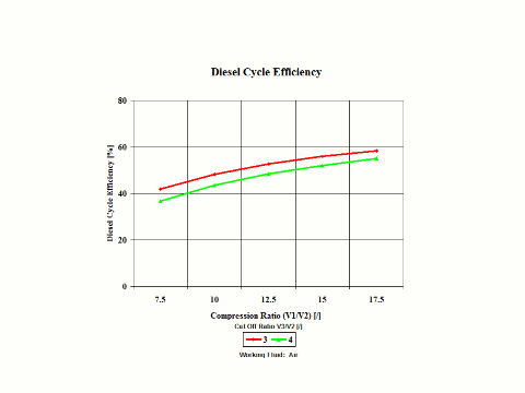
Figure 3 - Diesel Cycle Efficiency
Figure 4 presents the Diesel Cycle power output as a function of compression and combustion temperature values.
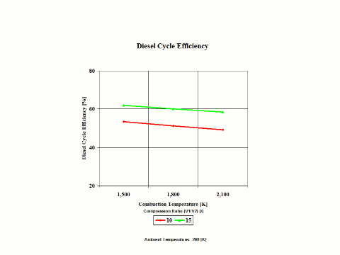
Figure 4 - Diesel Cycle Power Output
Figure 5 presents the Diesel Cycle cut off ratio as a function of the combustion temperature and compression ratio.
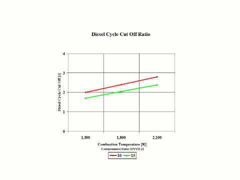
Figure 5 - Diesel Cycle Cut Off Ratio
Figure 6 presents the Diesel Cycle power output as a function of the combustion temperature and compression ratio. It should be noted that the number of revolutions is 60 [1/s] for given geometry of the four cylinder and four stroke Diesel engine.
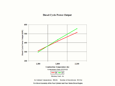
Figure 6 - Diesel Cycle Power Output
One can notice that the Diesel Cycle efficiency increases with an increase in the compression ratio and a decrease of the cut off ratio values. One can notice that the Diesel Cycle power output increases with an increase in the compression ratio and combustion temperature values.
Assumptions
Working fluid is air. There is no friction. Compression and expansion are isentropic -- there is no entropy change. Ideal gas state equation is valid -- pv = RT. Air behaves as a perfect gas -- specific heat has a constant value.
Governing Equations
T2/T1 = (V1/V2)^(ϰ-1)
V1/V2 = (T2/T1)^1/(ϰ-1)
T3/T4 = (V4/V3)^(ϰ-1)
V4/V3 = (T3/T4)^1/(ϰ-1)
ϰ = cp/cv
cp - cv = R
pv = RT
w = qh - ql
qh = cp(T3 - T2)
ql = cv(T4 - T1)
w = cp(T3 - T2) - cv(T4 - T1)
W = (cp(T3 - T2) - cv(T4 - T1))m
efficiency = 1 - (cut off ratio^ϰ - 1)/(ϰ(compression ratio^(ϰ-1))(cut off ratio - 1))
compression ratio = V1/V2
cut off ratio = V3/V2
Input Data
T1 = 298 [K]
p1 = 1 [atm]
compression ratio = 7.5, 10, 12.5, 15 and 17.5 [/]
cut off ratio = 3 and 4 [/]
R = 0.2867 [kJ/kg*K]
cp = 1.004 [kJ/kg*K]
ϰ = 1.4 [/]
Results
Diesel Cycle Efficiency
Diesel Cycle Efficiency
[%]
Cut Off Ratio
[/]
3
4
7.5
41.69
36.57
Compression
Ratio
[/]
10
48.03
43.4
12.5
52.46
48.29
15
55.81
51.93
17.5
58.45
54.80
Diesel Cycle Efficiency
Diesel Cycle
Efficiency
[%]
Compression Ratio
[/]
10
15
Combustion
Temperature
[K]
1,500
53.39
61.94
1,800
51.12
60.12
2,100
49.20
58.49
Diesel Cycle Cut Off Ratio
Cut Off Ratio
[/]
Combustion
Temperature
[K]
1,500
2.00
1.70
1,800
2.40
2.05
2,100
2.80
2.39
Diesel Cycle Power Output
Power Output
[kW]
Compression Ratio
[/]
10
15
Combustion
Temperature
[K]
1,500
311
297
1,800
417
433
2,100
514
557
Conclusions
The Diesel Cycle efficiency increases with an increase in the compression ratio and a decrase in the cut off rati values. Also, the Diesel Cycle power output increases with an increase in the compression ratio and combustion temperature values.
References
JANAF Thermochemical Data - Tables, 1970